 |

|
|
|
Conversion of an electric mini-guitar to electric octave mandolin
by Randy Cordle
Completed electric octave mandolin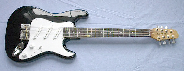
Shown is an electric octave mandolin that started its life as a
$99 mini-guitar. Total cost was approximately $200 with the additional
cost of items used in the conversion. The conversion process is
fairly simple, and can be done with the information given here if
you have some basic woodworking skills and a few basic power tools.
A drill press and 4" tabletop belt sander were the primary tools
that I used that may not be in everyone's shop, but the project
could be done using other methods.
Electric octave mandolin specifications
Additional parts and where they were obtained
Basic conversion process
Click on any of the following images for a larger view.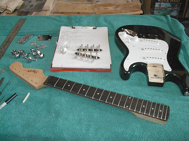
Mini-guitar disassembled and octave mandolin fingerboard width
marked out
Here the mini-guitar is disassembled in preparation for the
conversion to electric octave mandolin. The jack is unsoldered
so all components could be removed from the body during the
conversion. The fingerboard is marked to indicate the new 36mm nut width and 12th fret width of 47mm. A line is drawn connecting these two points and extended to the end of the fingerboard. The neck was sanded down to the new indicated width using a small 4" Delta bench top belt sander. Use a new medium grit belt and alternate between the two sides often to prevent the frets from becoming too hot. Keep the sides square so the neck will fit tightly in the neck pocket of the body after it is narrowed with added wood filler strips. The rear of the neck will later be reshaped. 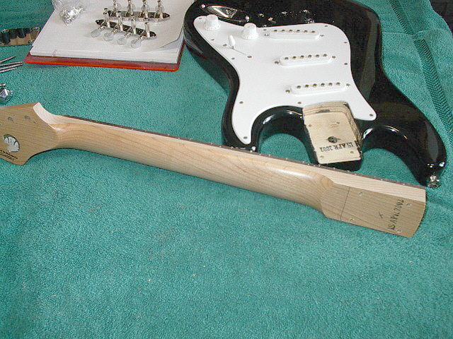
View showing flattened sides of neck after initial sanding
This view shows the neck side profile after it has been narrowed
to its correct dimensions. Before further work on the neck is
done, the fret ends should be re-beveled and rounded slightly.
This is done by running an 8" single-cut file down the length
of the neck while holding the file at a slight angle. This will
bevel the fret ends uniformly. Follow this with 150 grit sandpaper
held at the same angle as the fret end bevel. Finish by passing
a folded pad of 220 grit sandpaper over the ends of the frets.
Hold the sandpaper with the fingertips at the same angle as
the fret bevel and polish the ends of the frets. This will round
the ends slightly. Repeat this 220 sandpaper treatment until
all roughness is gone. The edge of the fingerboard can also
be slightly rounded for comfort. 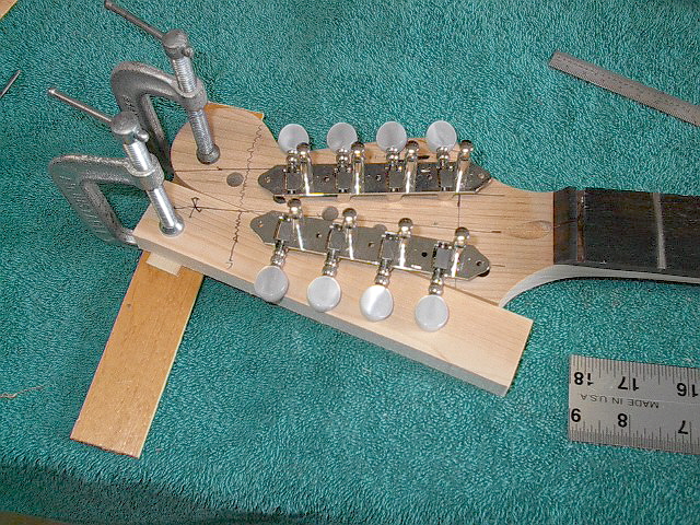
Laying out the location of new tuners
The existing headstock modification is carefully planned so
the new tuners can be accommodated by trimming the excess wood
from the treble side of the headstock, flipping it over, and
gluing it to the bass side. A small scrap of wood is clamped
to the bass side of the headstock and the new tuners are placed
in the correct position. The center of the string posts for
strings 1 and 8 are in line with the outside edges of the fingerboard.
The tuners are slanted inward so the mounting plates have approximately
1/8" clearance between them. Plan the tuner locations so the
waste area on the first and second string side can be cut off
and added to the other side. 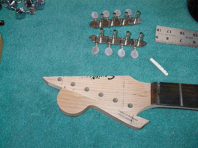
Altering the existing headstock profile
This photo should de-mystify the radical reshaping of the headstock. The waste area on the first and second string side is carefully cut, sanded flat, flipped, and glued to the bass side to build the headstock out to the necessary width to accommodate the new Schaller A-style tuners. Make certain all of the existing finish is removed from the gluing surfaces. Because the added wood comes from the same headstock, a near-perfect color match results in a barely-visible joint. 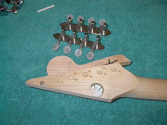
Original tuner post and mounting screw holes filled
The existing tuner holes are filled with short sections of 5/16"
dowel rod and the mounting screw holes are filled with pieces
of round toothpick. When the glue has dried these pieces can
be cut and sanded flush with the front and rear face of the
headstock. 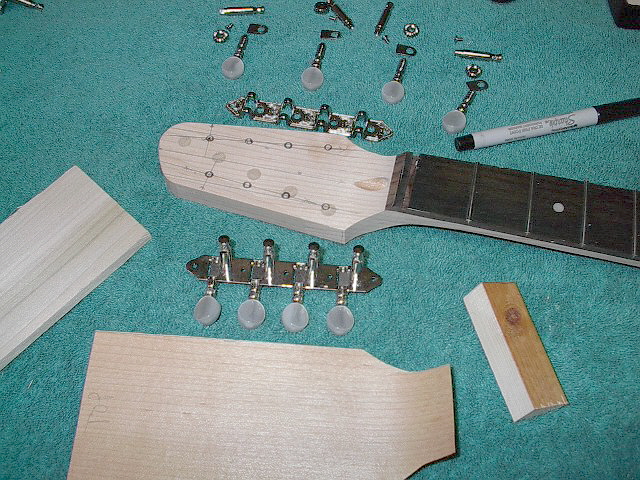
Cutting new headstock profile and layout of tuner shaft locations
The new profile is now drawn on the headstock's front face and
cut to shape. Layout the tuner locations. The tuner shaft centers are located 7/16" from the headstock edges. A small pilot hole can be drilled from the front side, then drilled out to 1/4" from the rear. 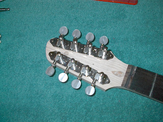
Tuners as they will be mounted
Tuners shown immediately before drilling through the headstock
and test fitting the tuner shafts. Drill the 1/4" tuner post holes out before applying the face veneer. The pre-bent veneer can now be added to the headstock face, making the modification almost invisible. The bent area of the veneer matches the area that curves up to the fingerboard. Two padded clamping cauls, one flat and the other curved, were used to clamp the overlay in position until dry. The only clue of the instrument’s original configuration is the filled tuner holes visible on the back side. After the face veneer is glued on, the 1/4" tuner shaft holes can be drilled through the headstock veneer. Make certain a backing board is clamped to the front face to prevent tear-out of the thin veneer face. 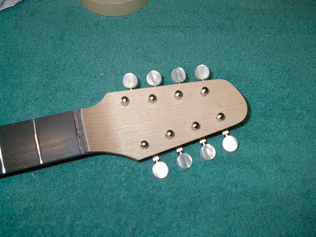
Checking tuner shaft fit
Check the fit of the new tuners. If they are slightly misaligned
or too tight the holes can be enlarged after the shaft bushing
counterbores are drilled. 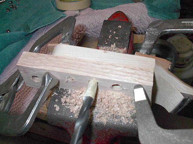
Counterboring the tuner shaft bushing holes
Clamp scrap stock to the front headstock face to prevent tear-out
when drilling the bushing counterbores. Drill 1/4" holes through
the scrap backing board from the rear of the headstock. These
holes will serve as pilot holes for the 3/8" bushing counterbore
bit. Use these pilot holes to drill partially through the headstock
with a 3/8" inch drill bit deep enough to allow the bushings
to seat against the face of the headstock. Mark the correct
depth with a bit of masking tape on the drill bit to ensure
not drilling all the way through. 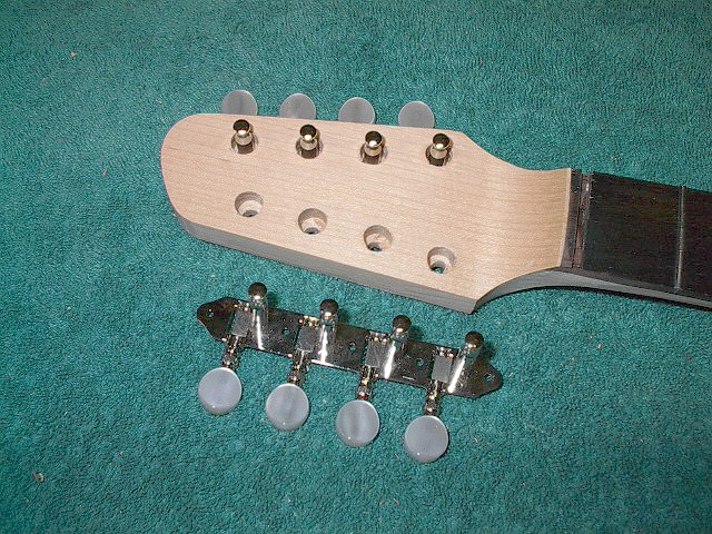
Tuner shaft bushing counterbores
The tuner shaft bushing counterbores can be seen here. NOTE:After having done this project, I would suggest that the tuner shaft holes be drilled out initially with a 3/8" bit. This eliminates the earlier drilling of the 1/4" tuner shaft holes. The two separate steps as outlined here contribute to the possibility of misalignment and the need to enlarge the 1/4" holes later to reduce friction caused from misalignment.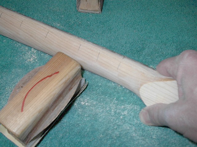
Re-profiling the neck shape
The neck was shaped by rounding the neck where the flat sides
were formed when the neck width was reduced to its new dimensions.
Start by sanding off the neck finish first and drawing several
pencil lines across the neck so sanding progress can be easily
monitored. Blend the rear of the neck smoothly up to match the
top of the fingerboard by the use of sandpaper held with a padded
holder. Start with 150 grit and work with progressively finer
grades until reaching 320 grit. The profile was left slightly
D-shaped to ensure that the neck would retain sufficient stiffness
to resist the pull of 8 strings. After the entire neck is sanded, apply 4 coats of Tru-oil to the entire neck. I then added a logo decal to the front face of the headstock and applied 3 more coats over the decal. 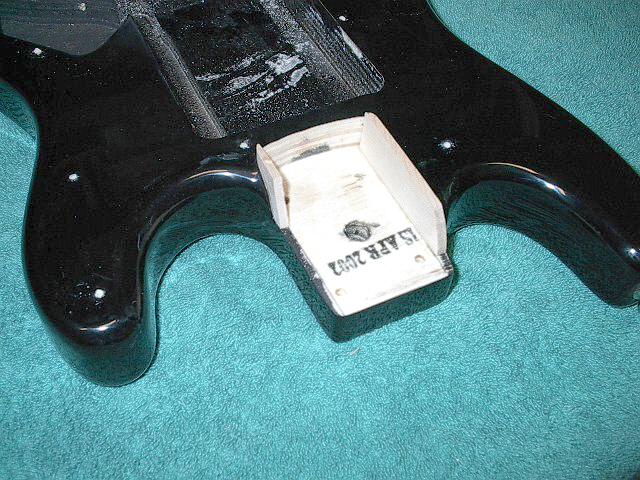
Filling extra neck pocket width
Reattach the neck temporarily and cut shims to fill the open
areas of the neck pocket. These areas were created as a result
of narrowing the neck. Mark the area of the neck pocket adjacent
to each side of the neck so these areas can be rounded over
to smoothly blend them into the neck. Remove the neck and glue
the shims in place. Trim the excess material from the neck pocket
shims and round over the extra width at the sides of the neck
pocket. Sand these areas with successively finer grades of sandpaper
until you have reached 320 grit. Protect areas of the body outside
of where you are working with wide masking tape. 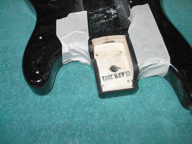
Touching up the new wood added to the neck pocket
Color the wood shims and other exposed bare areas with a black
Sharpie marker and let dry overnight. Apply three coats of Tru-oil
to match the original body finish. The touch-up isn't completely
invisible, but isn't very noticeable when the entire instrument
is assembled. 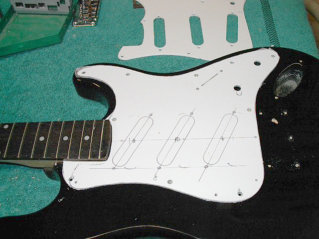
Fabricating the new pick guard
The original pick guard cutout for the neck is too wide for
the newly narrowed neck, so a new pick guard is in order. The
pick guard is also extended slightly at the neck area to better
cover the added neck pocket shims. The 3 pickup cutouts are
also slanted to approximately 10 degrees to better match the
pole pieces to the new string width. The volume knob was also
shifted downward about 1/2". NOTE:After having done this project, I would suggest that the pickup closest to the bridge be eliminated, ditch the tone control and move the volume knob to the original tone control location. I'd also change the 5-position selector switch to a 3 position Tele-style switch for front/both/rear pickup selection options. Also re-locate this switch and position it parallel to the strings to prevent bumping it while playing.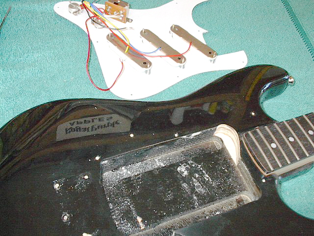
Extra wood removed from body cavity for neck pickup
A small area of the body route has been enlarged to accommodate
the pickup closest to the neck. This was the only area where
there was interference after the pickups were re-located. 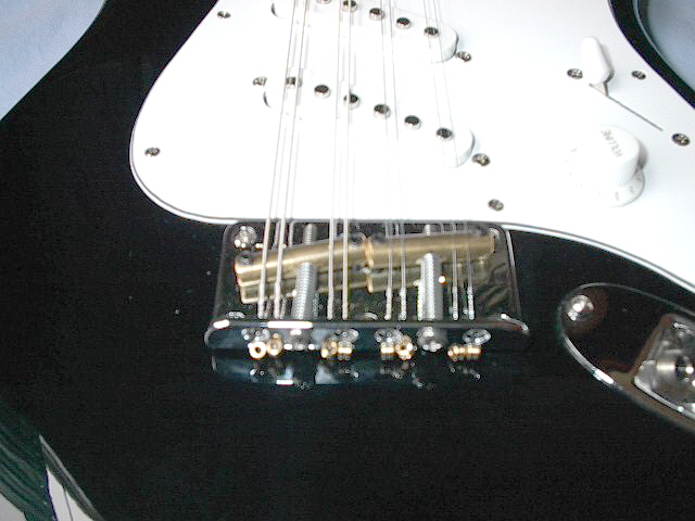
Modifying the original bridge for octave mandolin use
The pick guard assembly is screwed in position after positioning
the ground and jack wiring. A new jack is fitted to the mounting
plate, soldered, and mounted with its screws. The existing bridge was next modified for use as an octave mandolin bridge. The conversion was accomplished by adding new twin brass slanted saddles and drilling a 4 new string holes in the original bridge plate. 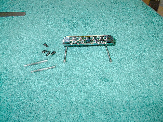
New holes drilled for additional strings
The existing saddle adjustment holes for the 2nd and 5th strings
were drilled out with a 9/64" drill for the new #6 X 32 X 1-1/2"
stainless steel saddle adjusting screws. The outer string holes were close enough to use them again for the outer-most G and E strings. New 1/8" holes were drilled immediately TOWARD THE CENTER from these holes to retain the additional G and E unison strings. The existing 3rd and 4th string holes become the new closest-to-center D and A string holes, with new 1/8" holes drilled immediately to the OUTSIDE of these holes to retain the additional D and A strings. Ideally all string pairs should be as close to 3 mm as possible. 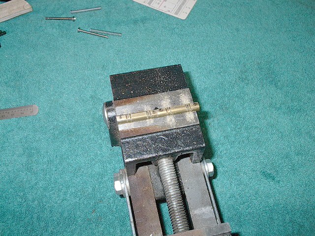
Drilling the saddle height adjustment screw holes
The saddles were formed from two 5/16" X 1-1/4"(33mm) pieces
of brass rod stock. The bottom 1/8" of each saddle was sanded
to create a flat area about 3/16" wide. This was done to facilitate
drilling the two #29 holes for the #8 X 32 X 3/8" allen head
saddle height adjustment setscrews. These holes are drilled
3mm from each saddle end to the center of the adjustment screw
hole. 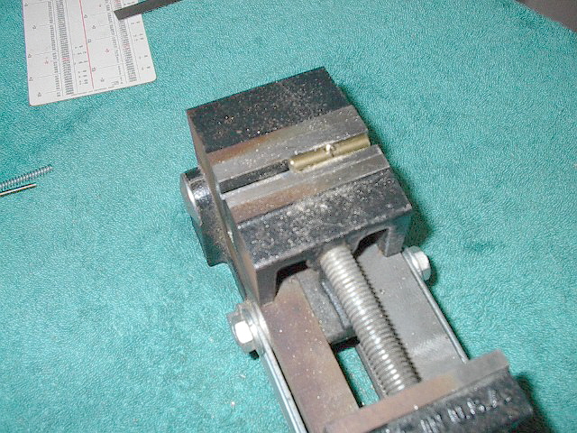
Drilling and tapping the holes for the intonation adjustment
screws
Two holes 7/64" in diameter are drilled at an approximate 5-degree
angle in the center of each saddle's face. Verify that you are
drilling the angled hole correctly so the saddles will slope
in the right direction. The bass side of each saddle angles
back toward the string attachment point of the bridge. These
holes are tapped for the #6 X 32 X 1-1/2" stainless steel saddle
intonation adjustment screws. A little candle wax on the tap
flutes will make the tapping job a bit easier. Round all sharp saddle edges and assemble the bridge using two 1-1/4" springs over the screws between the bridge plate and saddles. 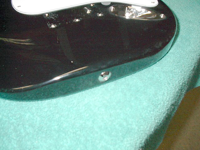
Adding my favorite locking strap hardware
The point where the original strap buttons were mounted were
drilled out with a 5/8" Forstner bit to a depth that allows
the new Straplok locking strap buttons to be flush with the
surrounding surface. These buttons are not necessary, but they
somehow find their way onto most of my stage instruments. 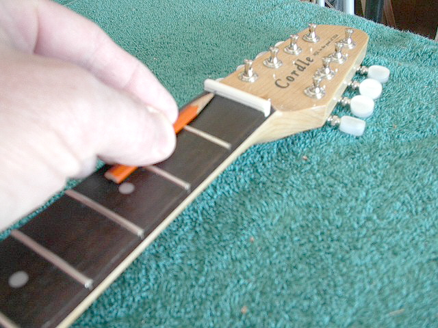
Adding a new nut
The octave mando is next fitted with a new nut after first trimming
the nut blank to the correct length. Sand the front and rear
face of the nut blank to achieve a tight fit in the nut slot.
Sand a wooden pencil down until it is reduced to a "half-pencil"
as shown here. Sharpen the point and mark a line on the face
of the nut by placing the half-pencil across the first and second
frets. This line will be used as a reference when cutting the
string slots. Remove the nut and carefully sand the edge of the blank to within 1/16" of this line. Use the disc portion of the Delta 4" belt/disc sander to reduce the height of the blank to the desired dimension. To do this safely, a zero-clearance table is used to allow the blank to be sanded without fear of it being caught and pulled between the table and the sanding disc. Adjust the table for about 3 degrees of tilt and sand a matching angle on a scrap of plywood that will be clamped to the top of the regular table to form the "zero-clearance" table. The slight tilt added to the top of the nut matches the angle of the headstock to add visual appeal. The nut is sanded down to within 1/16" of the reference line. 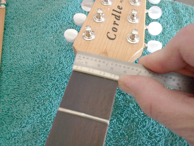
Layout of string position on new nut
The string positions are now marked on new nut in preparation
for cutting the new string slots. Use a 6" steel rule with mm
divisions to measure the distances from the bass edge of the
fingerboard. It is much easier to use the metric mm scale to
mark the locations than trying to use fractional equivalents.
For a 36mm nut width, the distances to the center of each nut
slot are 3.5mm, 7mm, 13mm, 16mm, 22mm, 25mm, 30mm, and 33mm. I used a fine tooth hobby backsaw to initially cut the slots into the nut to within 1/64th" of the indicated line. The saw I use has a 6" long blade and cuts a .020" kerf, but other similar small hobbiest saws are commonly available. Slope the cuts slightly downward toward the headstock face to ensure the string contacts the front edge of the nut when tensioned. The slots are widened by the use of small files to match the string diameters.
Final assembly and adjustment
String the instrument using 11, 16, 32,and 42 pairs of strings
from the GHS GBXL guitar string sets. Tune the strings to pitch
and adjust the depth of the nut slots by the use of appropriate
files until the proper action is achieved. I like to lower them
a little at a time until there is only a few thousandths clearance
above the first fret when pressing the string down between the
second and third fret locations. The correct depth should be
very close to the "half-pencil mark" that was created as a guide
to marking the initial nut slot depth. The saddle height is adjusted next by lowering the string saddles as low as possible without causing the strings to buzz against the fingerboard while being played. Adjust the saddles to match the radius of the fingerboard, also. Intonation is set to allow the instrument to sound the proper pitch along the entire length of the fingerboard. Intonation is adjusted by creating a harmonic at the 12th fret of the string being adjusted and matching its pitch to the fretted note played at the same location. The harmonic is a note that is twice the pitch of the open string and is created by LIGHTLY touching the string immediately above the 12th fret while picking the string. If the fretted note is LOWER than the harmonic, move the saddle TOWARD the fingerboard until they are the same. If the fretted note is HIGHER than the harmonic, move the saddle AWAY FROM the fingerboard until they are the same. With the slightly angled saddles, you should be able to set the intonation very closely for all strings. Adjust the initial pickup height so pickup pole pieces are 1/8" below the strings.
How does it sound? Any further ideas after playing it a while?
It sounds great; I was amazed at the fullness of sound this
little instrument produces. I play regular mando already, and
have added it to some of the tunes that I perform which lend
themselves to the fuller/deeper tone of this instrument. It's
possible shortcoming is the scale length is a little long to
cross over all the standard mandolin fingerings, but the sound
is great... especially when routed through a tube amp. You could
always capo at the first fret and drop the tuning a half step
if you desire a shorter scale. A little further down the road, I'll make a new pickguard for it and eliminate the pickup closest to the bridge. I'll shift the center pickup 3/4" toward the bridge at that time. Also, I'll eliminate the tone control, move the volume control to the existing tone control location, re-locate the pickup selection switch farther toward the bottom of the body and orient it parallel to the strings. I'll also change it to a 3 position Tele-style switch for front/both/rear pickup selection options. The switch will also be re-located to prevent bumping it while playing. If you're going to duplicate this project, I highly recommend you order a Tele selector switch and do these modifications to start with, then you'll be TOTALLY happy with your $200 octave! Contents of this page ©2004 Randy Cordle. All rights reserved.
|